Disassembly and assembly steps and key points of YB1 vane pump
Detailed steps and key points for disassembly and assembly Next, we will provide a detailed introduction to the disassembly and assembly process and key points of YB1 vane pump. By following these steps, you will be able to more easily complete the disassembly and assembly of the vane pump.
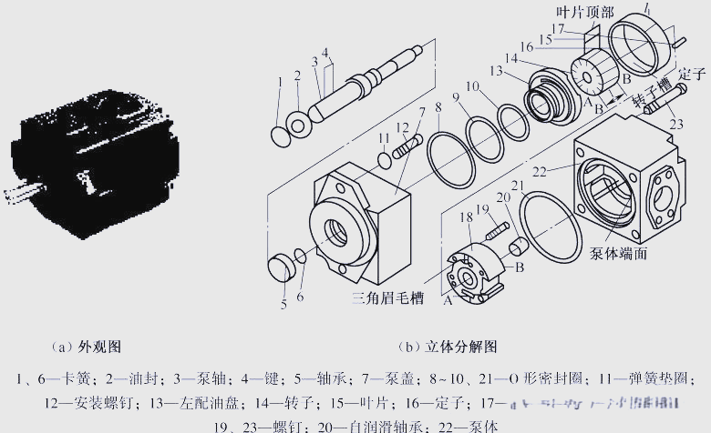
Overview of the entire disassembly and assembly process of YB1 vane pump Before starting to disassemble the YB1 vane pump, it is necessary to prepare a set of internal hexagonal wrenches, an oil resistant rubber plate, an oil pan, and other necessary tools and materials. Next, follow the steps below for disassembly and assembly: (1) Firstly, unscrew 4 screws 23 and remove pump cover 7. (2) Then, remove pump shaft 3. (3) Next, remove the components consisting of left oil distribution plate 13, right oil distribution plate 18, stator 16, rotor 14, etc., and separate them from pump body 22. (4) Finally, remove the sealing rings 8, 9, 10, 21 and other components one by one, and disassemble the left and right oil distribution plates, stator, rotor and other components one by one. By following the above steps, you will be able to easily complete the disassembly and assembly of YB1 vane pump. ① Firstly, unscrew screw 19 in order to remove left distribution pan 13, right distribution pan 18, and locating pin 17. ② Next, remove stator 16 and rotor blades 15 to observe the structure of each component in more detail. (7) During the disassembly process, the function and structure of the main components of the vane pump should be carefully observed. This includes the composition of the four circular arcs and four transition curves on the inner surface of the stator, the inclination angle and direction of the blade grooves on the rotor blades, the structure of the oil distribution plate, and the functions of the suction port, pressure port, triangular groove, annular groove, and groove bottom hole. Meanwhile, it is also important to observe the position and form of the sealing rings used in the pump. (8) When assembling, it is necessary to follow the reverse order of disassembly. Before assembly, all components should be cleaned and lubricating fluid should be applied to each mating surface. At the same time, attention should be paid to the assembly of seals at all locations to ensure that the rotation direction of the pump shaft matches the suction port of the pump. (9) After assembly, it is necessary to tidy up the site to ensure the cleanliness and efficiency of the work.
The above:
Analysis of the causes of damage to the accumulator bladder and solutions 


 Pressure switch